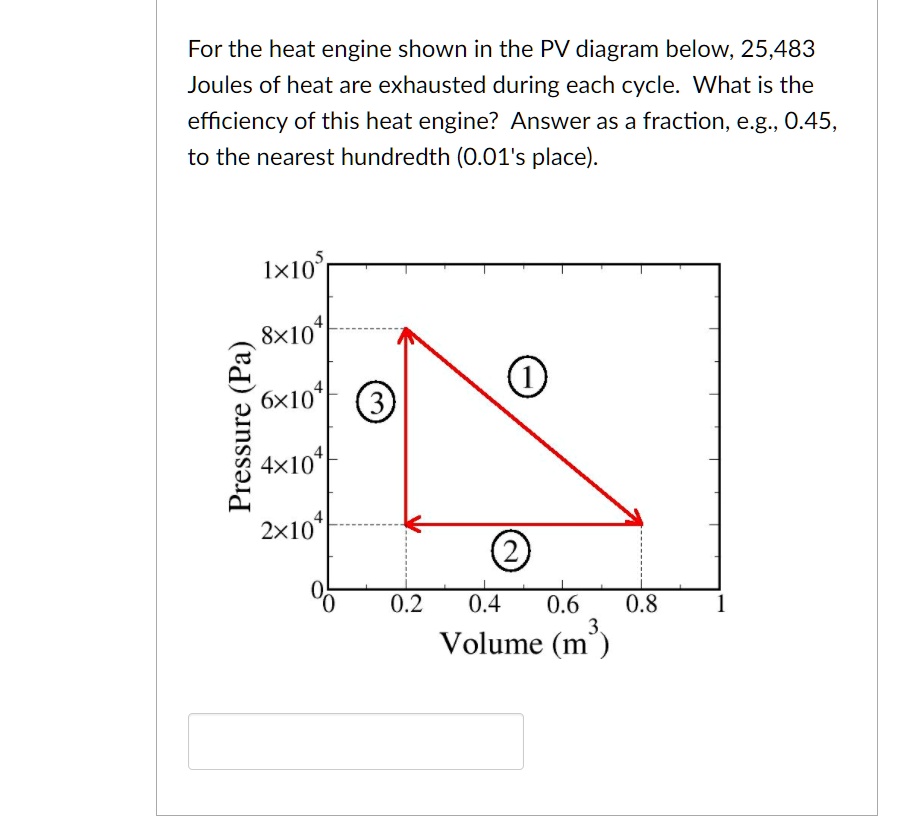
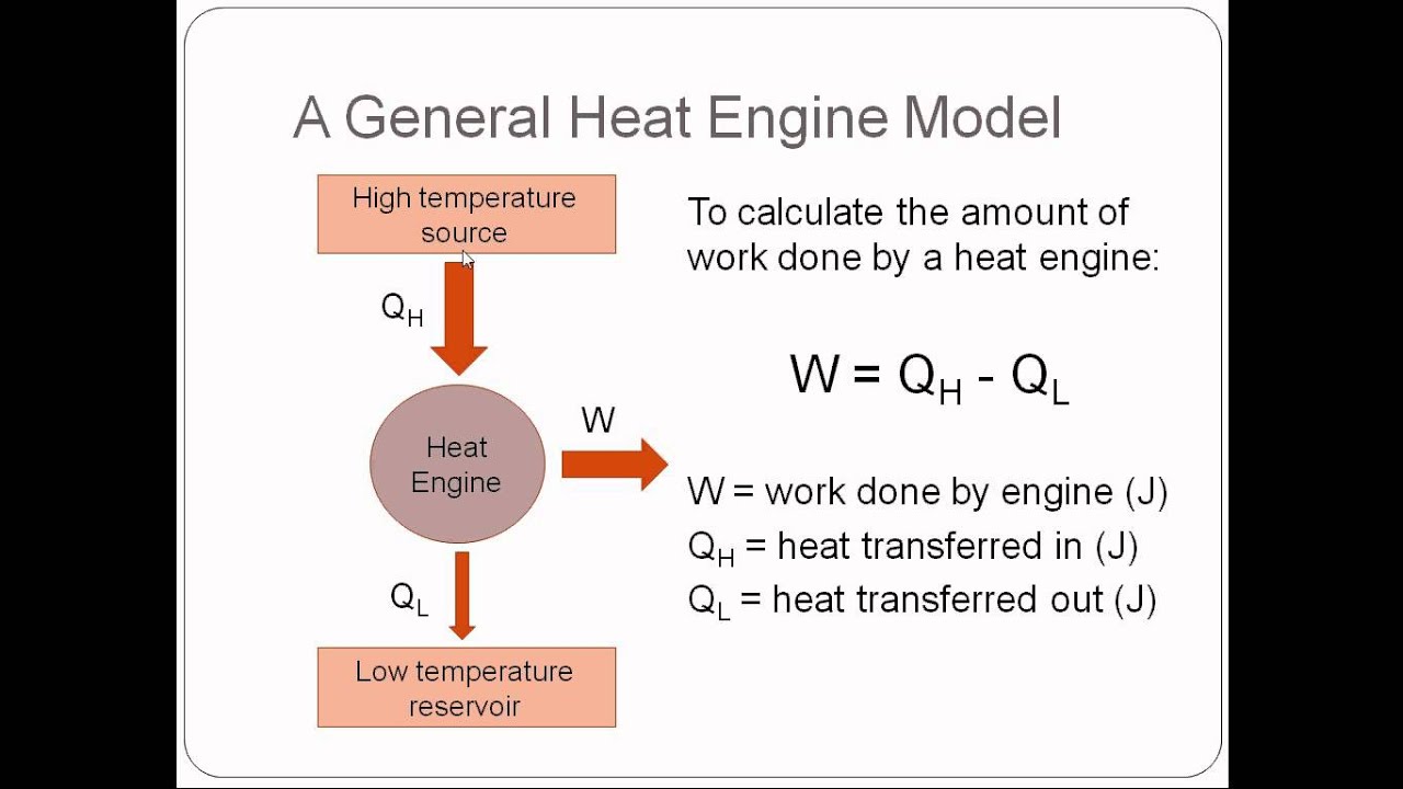
SOLVED For the heat engine shown in the PV diagram below, 25,483 Joules of heat are exhausted
Carnot Cycle - Carnot Heat Engine pV diagram of Carnot cycle. The area bounded by the complete cycle path represents the total work that can be done during one cycle. The second law of thermodynamics places constraints upon the direction of heat transfer and sets an upper limit to the efficiency of conversion of heat to work in heat engines.

A schematic explaining the heat engine invented by Savery to pump water... Download Scientific
Any heat engine employing the Carnot cycle is called a Carnot engine. Figure 15.4.1 15.4. 1: This novelty toy, known as the drinking bird, is an example of Carnot's engine. It contains methylene chloride (mixed with a dye) in the abdomen, which boils at a very low temperature—about 100oF 100 o F. To operate, one gets the bird's head wet.
HEAT ENGINES
Overview In thermodynamics, heat engines are often modeled using a standard engineering model such as the Otto cycle. The theoretical model can be refined and augmented with actual data from an operating engine, using tools such as an indicator diagram.

Schematic diagram of the Stirling heat engine cycle Download Scientific Diagram
A PV diagram illustrates the process occurring in heat engines at the constant mass of gas. A PV diagram is in a closed loop, representing the amount of work done during a cycle. A PV diagram depicts volume on the horizontal axis and pressure on the vertical axis. Each point of the PV diagram represents states of different stages of gas.
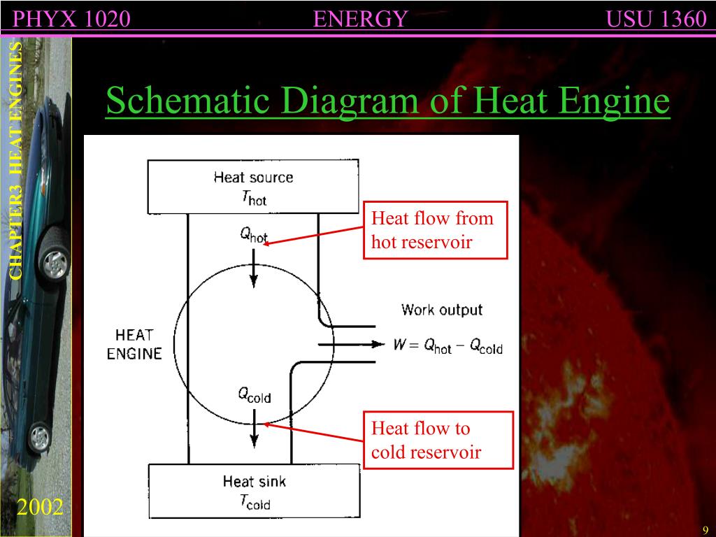
PPT CHAPTER 3 HEAT ENGINES PowerPoint Presentation, free download ID6948148
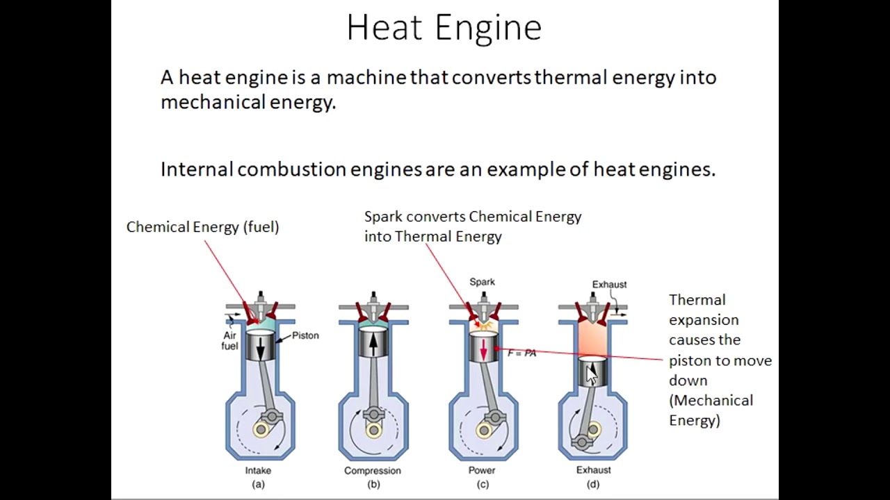
A heat engine is a mechanical machine that changes the thermal or heat energy of the fuel into mechanical power, which is further used to perform useful work. This is achieved by moving the work material from a higher temperature to a lower temperature. When someone rubs his hand one on the other hand, then friction produces due to rubbing.
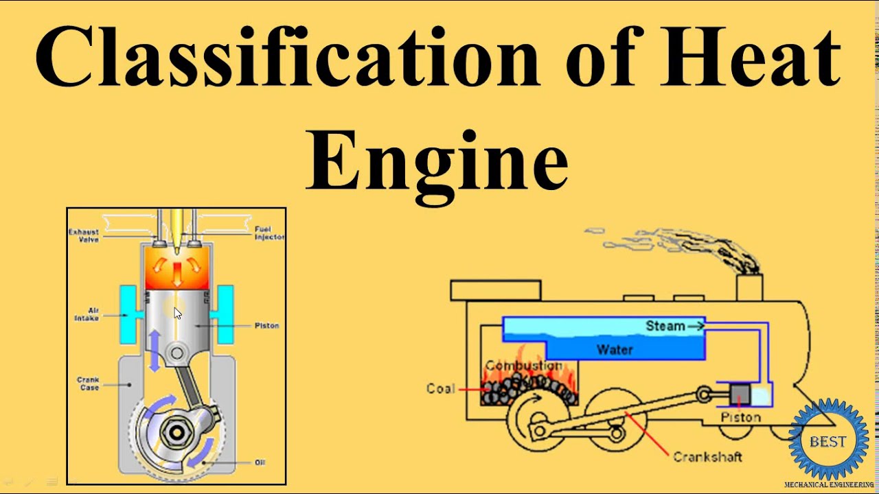
Classification of Heat Engine YouTube
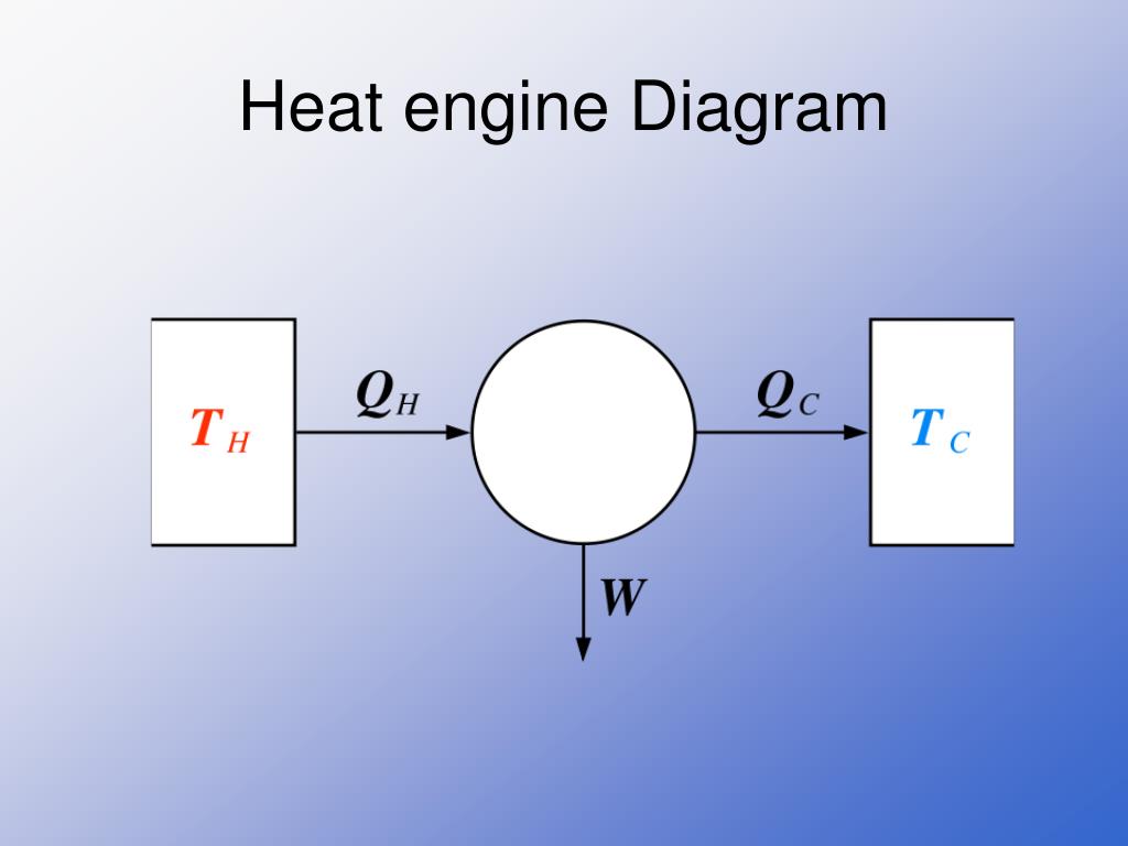
Heat engine diagram. Thermodynamic power cycles are the basis for the operation of heat engines, which supply most of the world's electric power and run the vast majority of motor vehicles. Power cycles can be organized into two categories: real cycles and ideal cycles. Cycles encountered in real world devices (real cycles) are difficult to.
Microscopic Heat Engine Demonstrated
The T-s diagram in Figure 6.1.2 illustrates the four processes in a Rankine cycle: Water at a low pressure and a low temperature (state 1) is pumped to a boiler.. In other words, a heat engine cannot convert all the heat supplied by the heat source (e.g., boiler) to useful work, even under ideal conditions. Thermal efficiency is a.
Heat Engine Heat Engine And Second Law Of Thermodynamics Gambaran
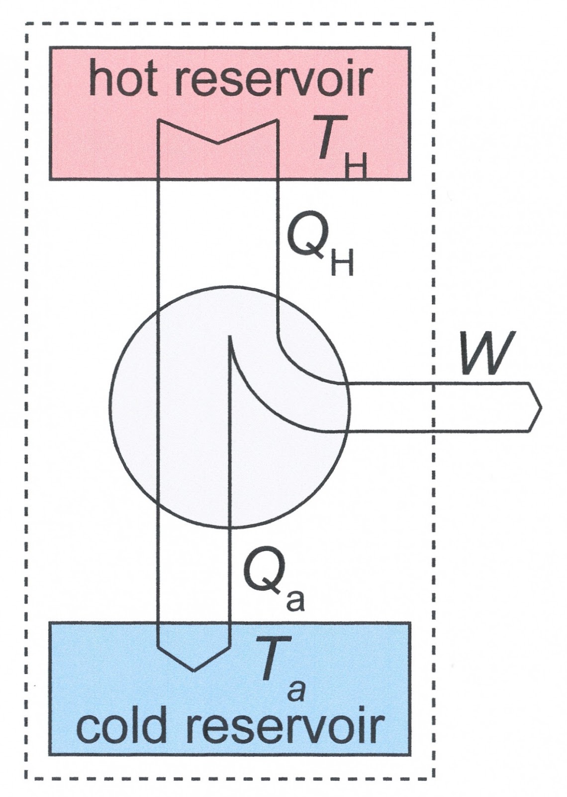
Figure 8.9.2 8.9. 2: Schematic representation of a heat engine, governed, of course, by the first law of thermodynamics (and other laws of thermodynamics we will discuss later). Figure 8.9.3 8.9. 3: (a) Heat transfer to the gas in a cylinder increases the internal energy of the gas, creating higher pressure and temperature.
PPT THERMODYNAMICS PowerPoint Presentation, free download ID4040289
A heat engine is a device used to convert heat energy into mechanical work which is useful for people. It uses a simple apparatus to perform the procedure. The heat engine processes several advantages along with few limitations. Classification of Heat Engine We have five different types of heat engines.
Schematic Diagram Of Heat Engine Free Image Diagram
A heat engine does exactly this—it makes use of the properties of thermodynamics to transform heat into work. Gasoline and diesel engines, jet engines, and steam turbines that generate electricity are all examples of heat engines. Figure 12.13 illustrates one of the ways in which heat transfers energy to do work.

Schematic Diagram Of Heat Engine College physics, Thermodynamics, Chinese academy of sciences
Engine Cycles. For a constant mass of gas, the operation of a heat engine is a repeating cycle and its PV diagram will be a closed figure. The idea of an engine cycle is illustrated below for one of the simplest kinds of cycles. If the cycle is operated clockwise on the diagram, the engine uses heat to do net work.
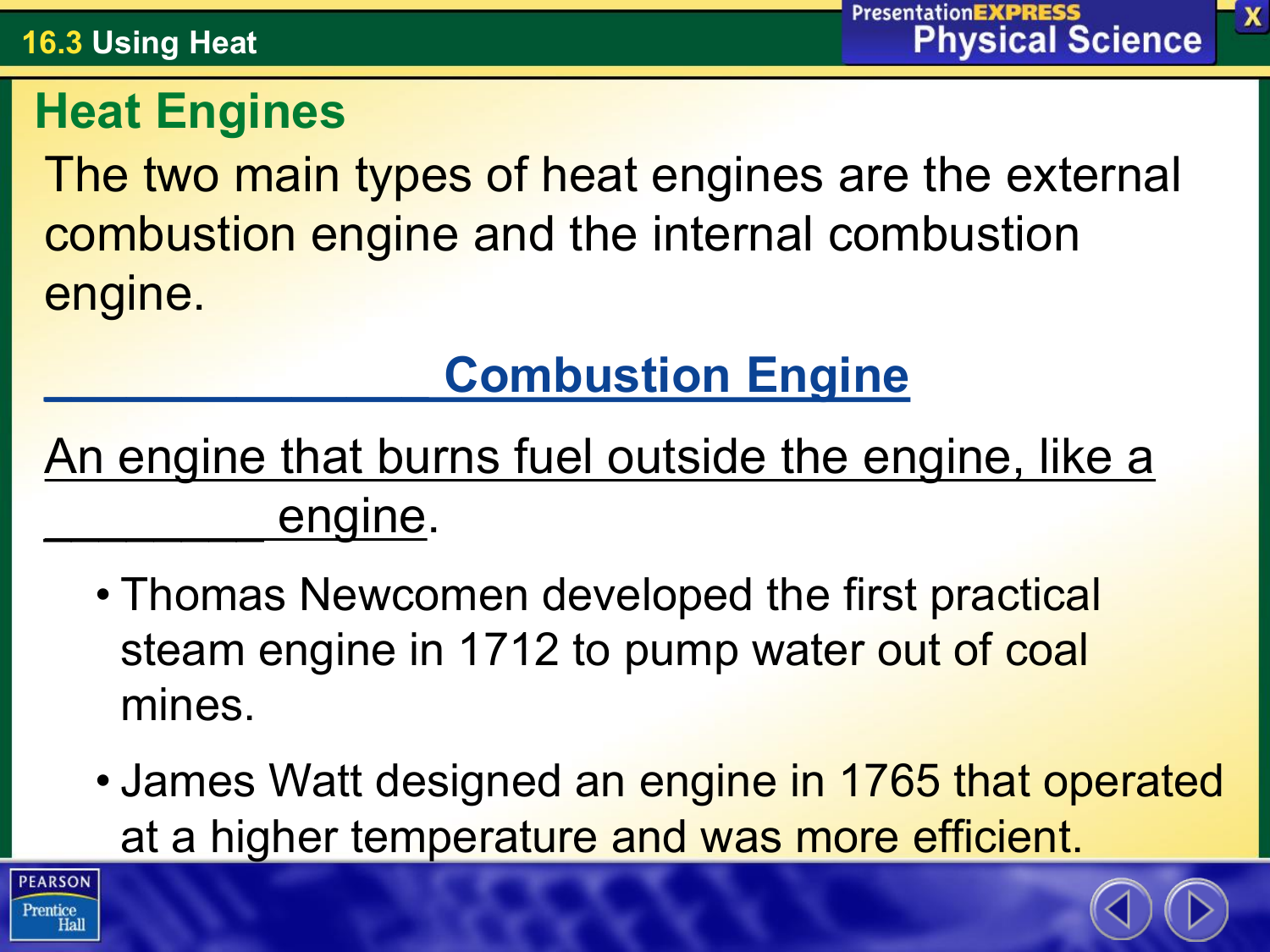
The two main types of heat engines are the external engine.
The heat engine is a device that converts heat energy into mechanical energy, i.e., to the ability with which we can work. It is widely used these days as it helps to transform the heat into something productive. Read on to learn more about its working, efficiency, types, examples and applications. Heat Engine
Heat Engine Concept Of Heat Engine Gambaran
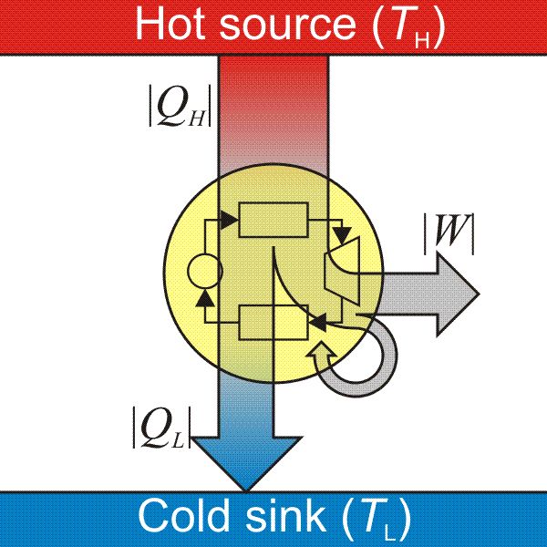
Carnot engine diagram (modern) - where an amount of heat QH flows from a high temperature TH furnace through the fluid of the "working body" (working substance) and the remaining heat QC flows into the cold sink TC, thus forcing the working substance to do mechanical work W on the surroundings, via cycles of contractions and expansions.

PPT Lecture 11. Real Heat Engines and refrigerators (Ch. 4) PowerPoint Presentation ID1739008
This physics video tutorial provides a basic introduction into heat engines. it explains how to calculate the mechanical work performed by a heat engine usi.
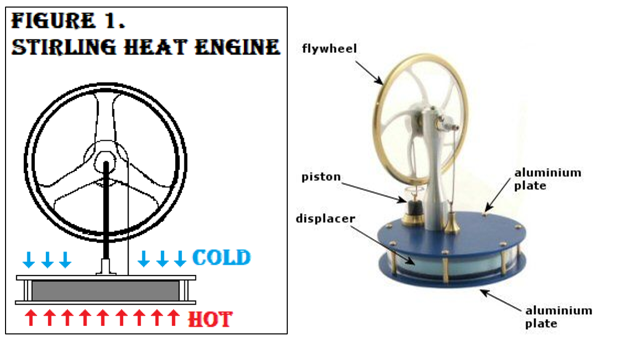
Stirling Heat Engine (Body Page)
We will use a steam engine to illustrate how heat is converted to work in heat engines. A typical steam engine consists of four main equipment: boiler, turbine, condenser, and pump, as shown in Figure 6.1.1. The T-s diagram in Figure 6.1.2 illustrates the four processes in a Rankine cycle:

PPT Chapter11 Heat Engines and the Laws of Thermodynamics PowerPoint Presentation ID1529174
A very basic diagram of the heat engine is given below: We know that thermodynamics is the study of the relation between heat and work. The first law of thermodynamics and the second law of thermodynamics help in the operation of the heat engine.