
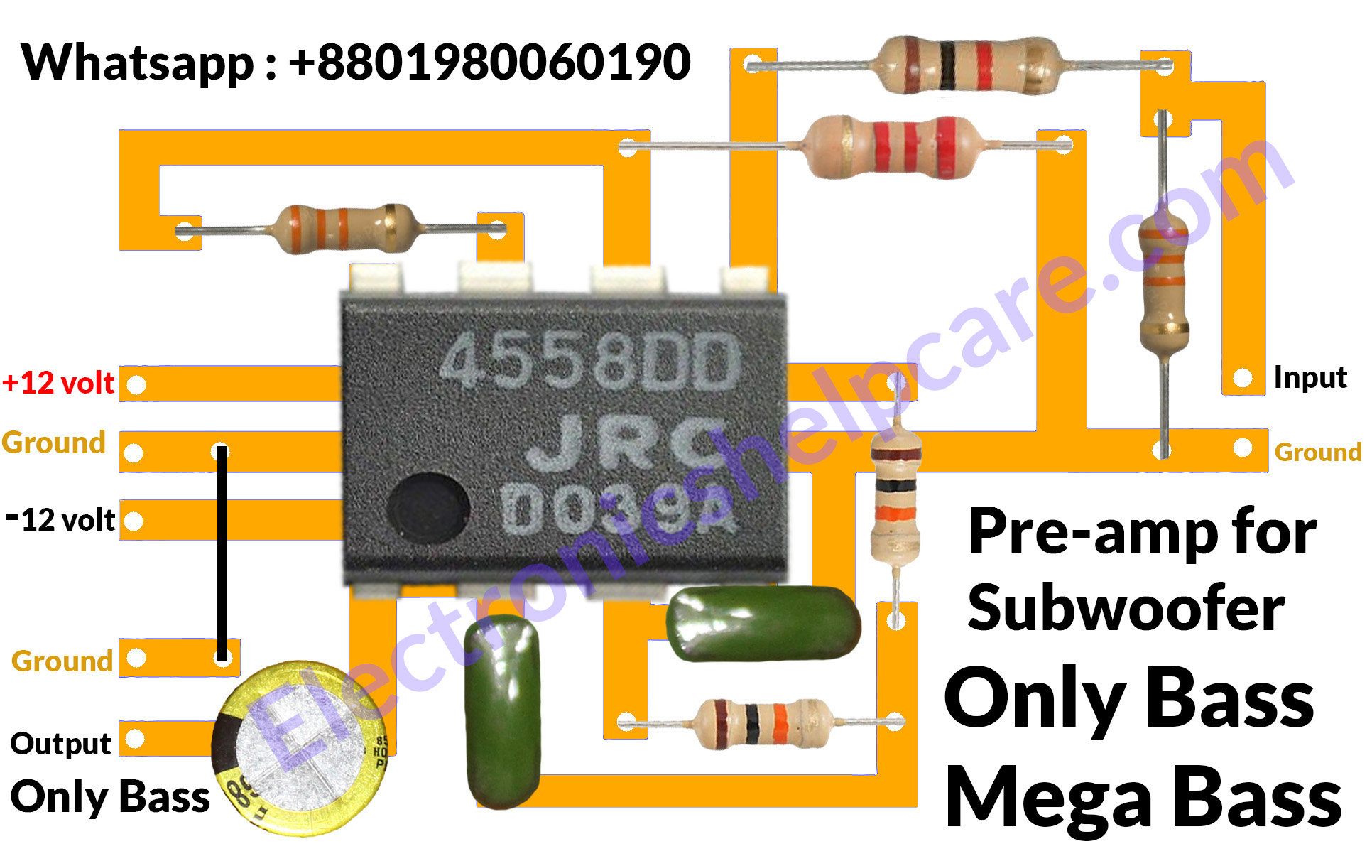
Pin on ic4558
A low pass filter circuit Bass Booster is an essential component in audio systems that enhances the bass frequencies of an audio signal. The JRC4558 IC, an integrated circuit, is widely used in low pass filter circuits due to its superior performance and versatility. This circuit is known for its ability to isolate low-frequency sounds and.

4558 Ic Circuit Diagram
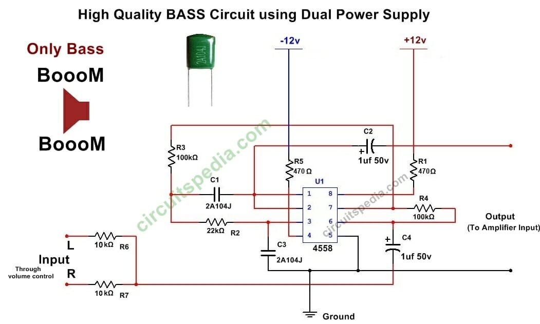
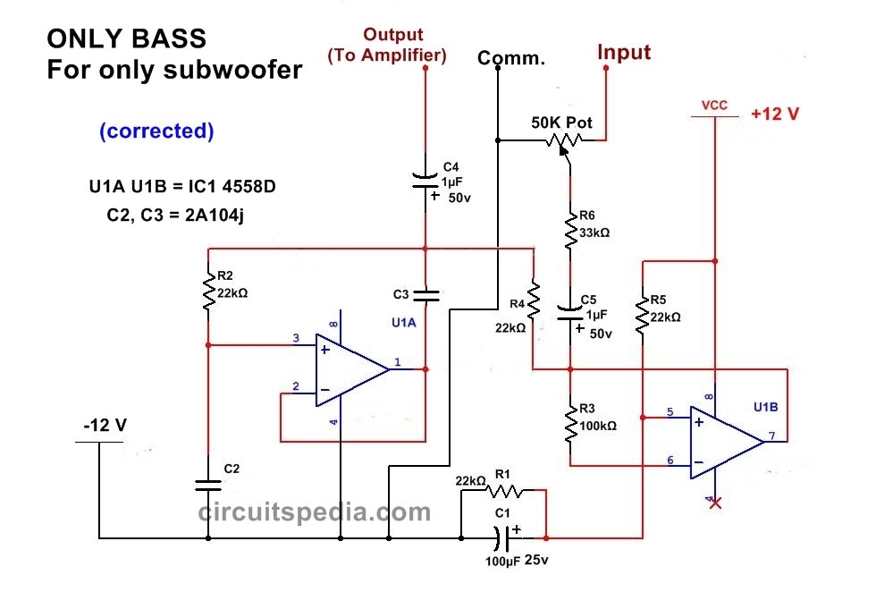
In this video how to build a simple, high-quality bass booster circuit for a subwoofer with IC 4558D. This circuit can be connected to many other amplifiers.

12 Volt 4558 Ic Subwoofer Circuit Diagram Parts Zoya Circuit
28 Share 1.8K views 4 months ago INDIA #4558D ,4558 ic full diagram /4558D subwoofer circuit diagram/Mr electro About this videomore.more 4558 ic bass circuit | only bass |.
4558 Circuit Diagram
In this video, we are going to show you making a bass booster circuit using 4558 IC. If you need extra bass, then you can apply this circuit. This circuit ha.
Subwoofer 4558 Ic Bass Treble Circuit Diagram / How to make bass
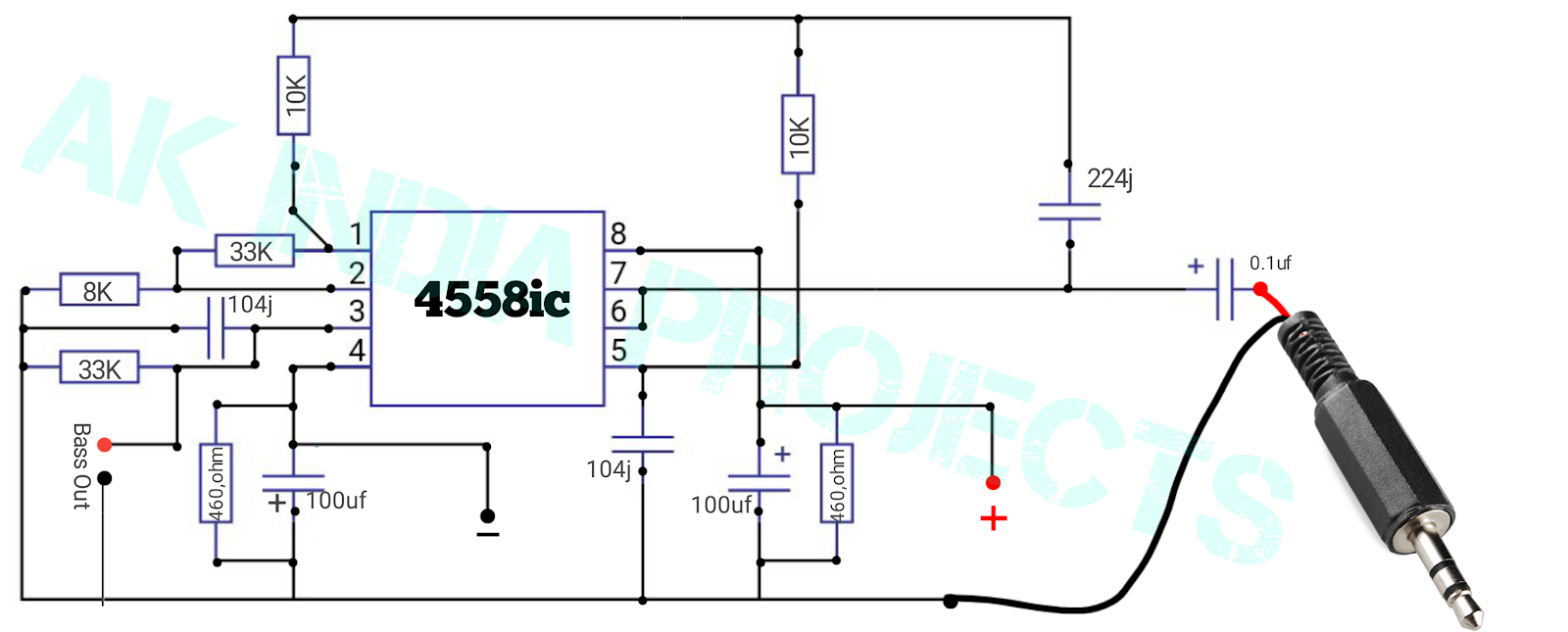
This is The Circuit Only For BASS Booster using 4558 ic, By using this bass circuit for woofer the audio is bass Boosted . This circuit Give Clear Bass Without Any Disturbance. If You Need to extra bass Then you can apply this circuit Bass Control circuit. So Only Give The Output Of This to Bass Speaker (Woofer) only.

12 Volt 4558 Ic Subwoofer Circuit Diagram Diagram Schemas Wiring
4558 ic subwoofer circuit || low pass filter Board connection || Electronics verma Electronics Verma 288K subscribers Join Subscribe 499 Save 22K views 10 months ago #lowpassfilter.
4558 Ic Subwoofer Circuit Diagram Pdf Home Wiring Diagram
ic 4558 Subwoofer Bass Booster Circuit diagram , bass circuit for woofer - Read online for free. ic 4558 Subwoofer Bass Booster Circuit diagram , bass circuit for woofer

Full bass 4558 ic subwoofer speakers control (100 Working) YouTube
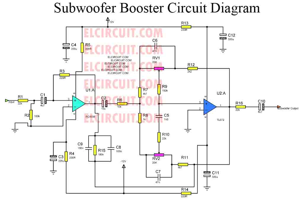
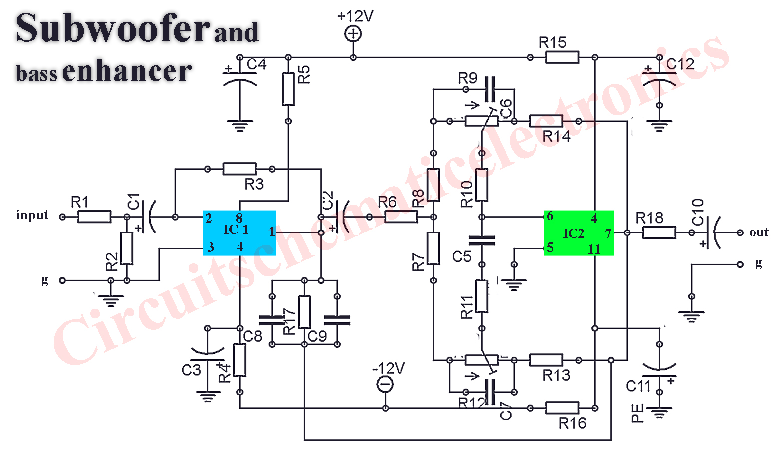
The circuit that I publish, is a circuit of modules that use the subwoofer amplifier ic op-amp 4558 which acts as a reinforcement of bass tones (subwoofer) assisted of it's by the workings of some supporting components such as resistors, capacitors.

4558 Ic Audio Equalizer Circuit Diagrams Circuit Diagram
Circuit Diagram Components Required What is a Low Pass Filter? A low-pass filter (LPF) circuit is a filter that passes signals with a frequency lower than a selected cut-off frequency and attenuates signals with frequencies higher than the cut-off frequency. The exact frequency response of the filter depends on the filter design.
Ic 4558 Preamp Circuit Diagram Pdf Wiring Diagram
Pin Off 4558d Ic|4558d subwoofer circuit diagram|4558d bass circuit|Mr Electro #4558 #4558d_bass_circuit#mrelectro 4558 ic bass circuit4558 ic subwoofer ci.

Skema Echo Ic 4558 Subwoofer Circuit Diagram Using Ic 4558 Home
Low Pass Filter for Subwoofer With 4558D IC: In this project I will show you how you can make a Low Pass Filter with 4558D IC for Subwoofer.. Connect this pin with ground and your circuit will be turn on and works. Plz replay if your problem solved. Thanks . 0. kh025104. Question 4 years ago on Step 3. Answer Upvote. sir 4558 low pass filter.
how to make subwoofer circuit diagram Electronics Help Care
The IC 4558 is a popular operational amplifier (op-amp) used in audio applications and is commonly used in subwoofer circuits. The layout of the subwoofer IC 4558 is an important factor in achieving high-quality sound reproduction. The layout of the IC affects the performance of the subwoofer, and a well-designed layout can significantly.

4558 Ic Subwoofer Circuit Circuit Diagram
One popular subwoofer preamplifier that incorporates a low pass filter circuit is the 4558 subwoofer preamplifier, which utilizes the JRC4558 integrated circuit (IC). In this article, we will dive into the specifications of the JRC4558 IC and discuss the importance and functionality of the low pass filter circuit in a subwoofer preamplifier.
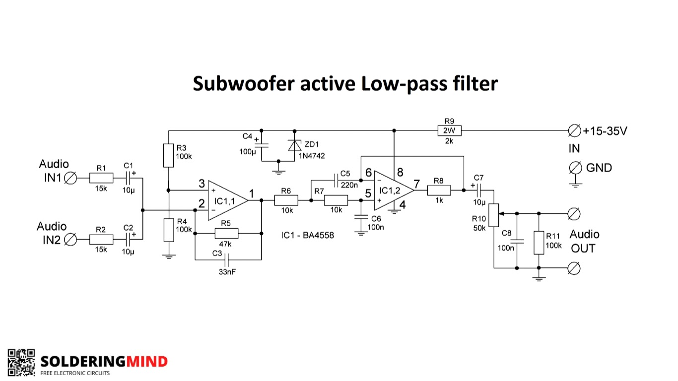
Low pass filter circuits using 4558 IC Soldering Mind
The 4558 circuit subwoofer wiring diagram is incredibly versatile and can be used to create a variety of different car audio systems. There are several ways in which it can be modified to produce the desired sound quality, such as adjusting the resistance of the resistor network or adding additional components such as capacitors or inductors..
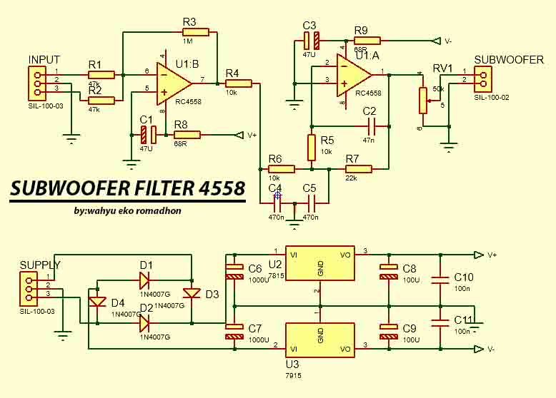
Engenharia Circuito Filtro de Subwoofer 4558 complete Regulated Power
The 4558 IC subwoofer bass booster low pass filter circuit uses a combination of resistor-capacitor networks, op-amps, and inductors to filter and enhance low-frequency sounds. The low-pass filter network filters out the high-frequency signals, leaving only the low-frequency sounds.
ic 4558 Subwoofer Bass Booster Circuit diagram , bass circuit for woofer
The 4558 IC operates on a supply voltage range of ±4V to ±18V and provides excellent signal-to-noise ratio, low noise output, and high common-mode rejection ratio. Due to its versatile characteristics, this IC can be used for various purposes, including audio pre-amplification and tone control circuits. TDA2030 Subwoofer Amplifier Circuit.